Weekend Project: New Quadcopter Landing Gear

My quadcopter has been collecting dust for about a year because of broken landing gear from a hard landing. I decide last weekend that it was time to fix that.
I'd been using some Lego to as landing gear to give room for my Tarot GoPro gimbal. See here:
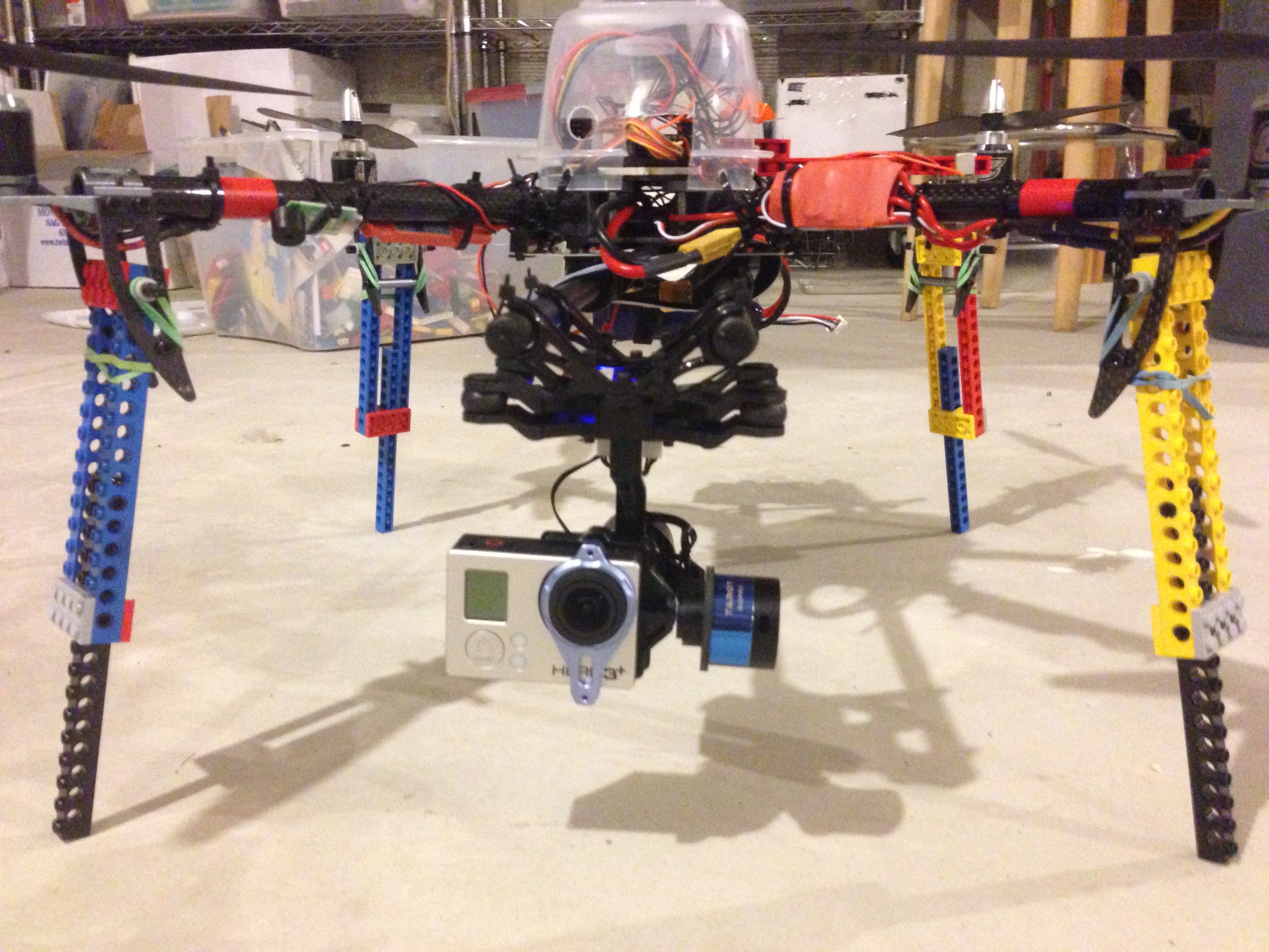
I've broken a few of those Lego beams, so I decided I needed something different.
Since I have a Printrbot Simple 3D Printer, I figured I could design some new landing gear and print them out.
Design
Lately, my goto application for 3D design is OpenSCAD. OpenSCAD uses 3D objects to compose your 3D model. OpenSCAD also uses a scripting language to create objects rather then click and drag techniques. Being that I'm a software engineer, this method works nicely for me, but shouldn't scare off non-programmer's.
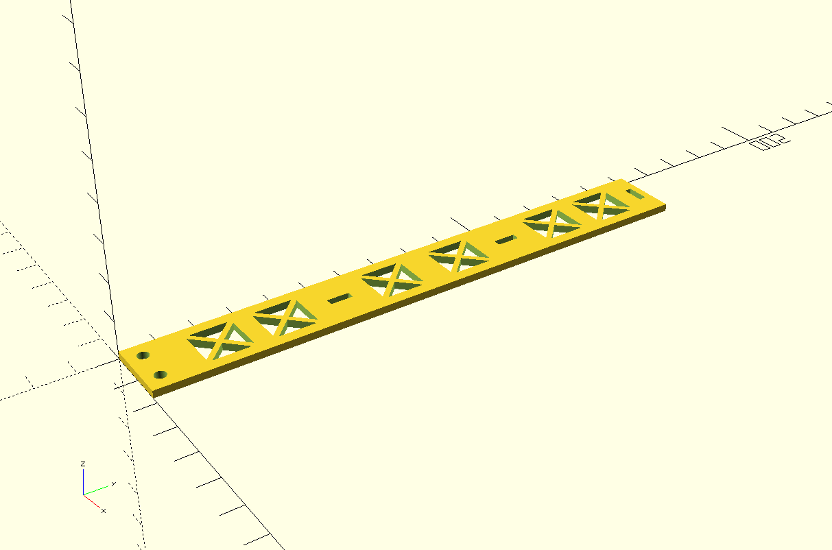
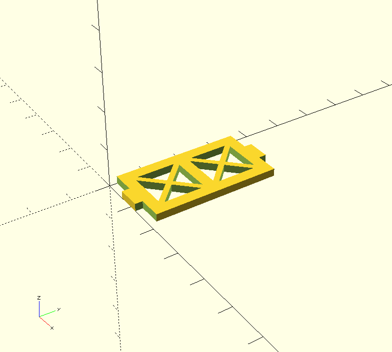
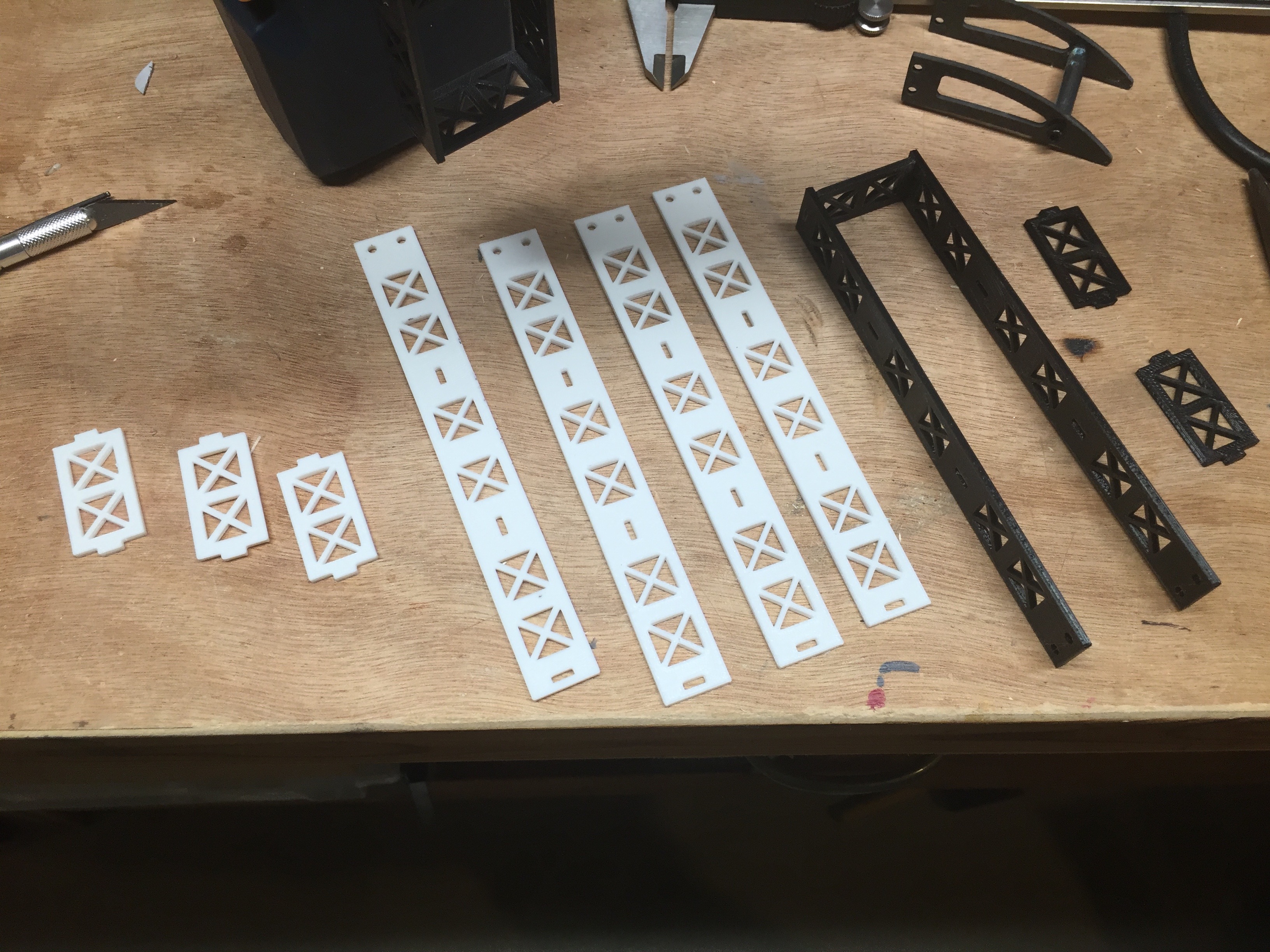
My design for landing gear would be composed of two distinct parts, which I'll call a strut and a cross. To make one leg I'd need 2 struts and 3 crosses. Here's what the pieces look like and the script to create them.
Strut
$fn=100;

module triangle(w, h) {
    linear_extrude(height=h) {
        polygon([[0,0],[w,0],[w/2,(w/2)*tan(45)]]);
    }
}

module grid(w,h) {
    translate([1,0,0]) triangle(w,h);
    translate([0,w+1,0]) rotate(-90) triangle(w,h);
    translate([w+1,w+2,0]) rotate(180) triangle(w,h);
    translate([w+2,1,0]) rotate(90) triangle(w,h);
}

difference() {
    cube([18,150,2]);
    translate([4.5,4,0]) cylinder(h=3,d=3);
    translate([13.5,4,0]) cylinder(h=3,d=3);

    translate([8,50,0]) cube([2,6,3]);
    translate([8,100,0]) cube([2,6,3]);
    translate([6,146,0]) cube([6,2,3]);

    translate([3,15,0]) grid(10,3);
    translate([3,32,0]) grid(10,3);

    translate([3,62,0]) grid(10,3);
    translate([3,82,0]) grid(10,3);

    translate([3,112,0]) grid(10,3);
    translate([3,129,0]) grid(10,3);
}
This code could be cleaned up a bit, but it did the job. Using Modules really simplified things.
Cross
module triangle(w, h) {
    linear_extrude(height=h) {
        polygon([[0,0],[w,0],[w/2,(w/2)*tan(45)]]);
    }
}

module grid(w,h) {
    translate([1,0,0]) triangle(w,h);
    translate([0,w+1,0]) rotate(-90) triangle(w,h);
    translate([w+1,w+2,0]) rotate(180) triangle(w,h);
    translate([w+2,1,0]) rotate(90) triangle(w,h);
}

difference() {
    cube([18,37,2]);
    cube([6,2,2]);
    translate([12,0,0]) cube([6,2,2]);
    translate([0,35,0]) cube([6,2,2]);
    translate([12,35,0]) cube([6,2,2]);

    translate([3,5,0]) grid(10,3);
    translate([3,20,0]) grid(10,3);
}
There's probably a way to have common library for modules and import it, but I'll have to look into that.
With the design finished I was able export the model to STL format right form OpenSCAD.
I loaded the STL file into Cura to do the slicing and then exported the GCode. My rough parameters where:
- Layer height: 0.2mm
- Shell thickness: 0.8mm
- Bottom/Top thickness: 0.6mm
- Fill Density: 50%
- Printing temperature: 200 C
- Bed temperature: 70 C
I loaded the GCode into my OctoPi version of Octoprint, and printed out the pieces.
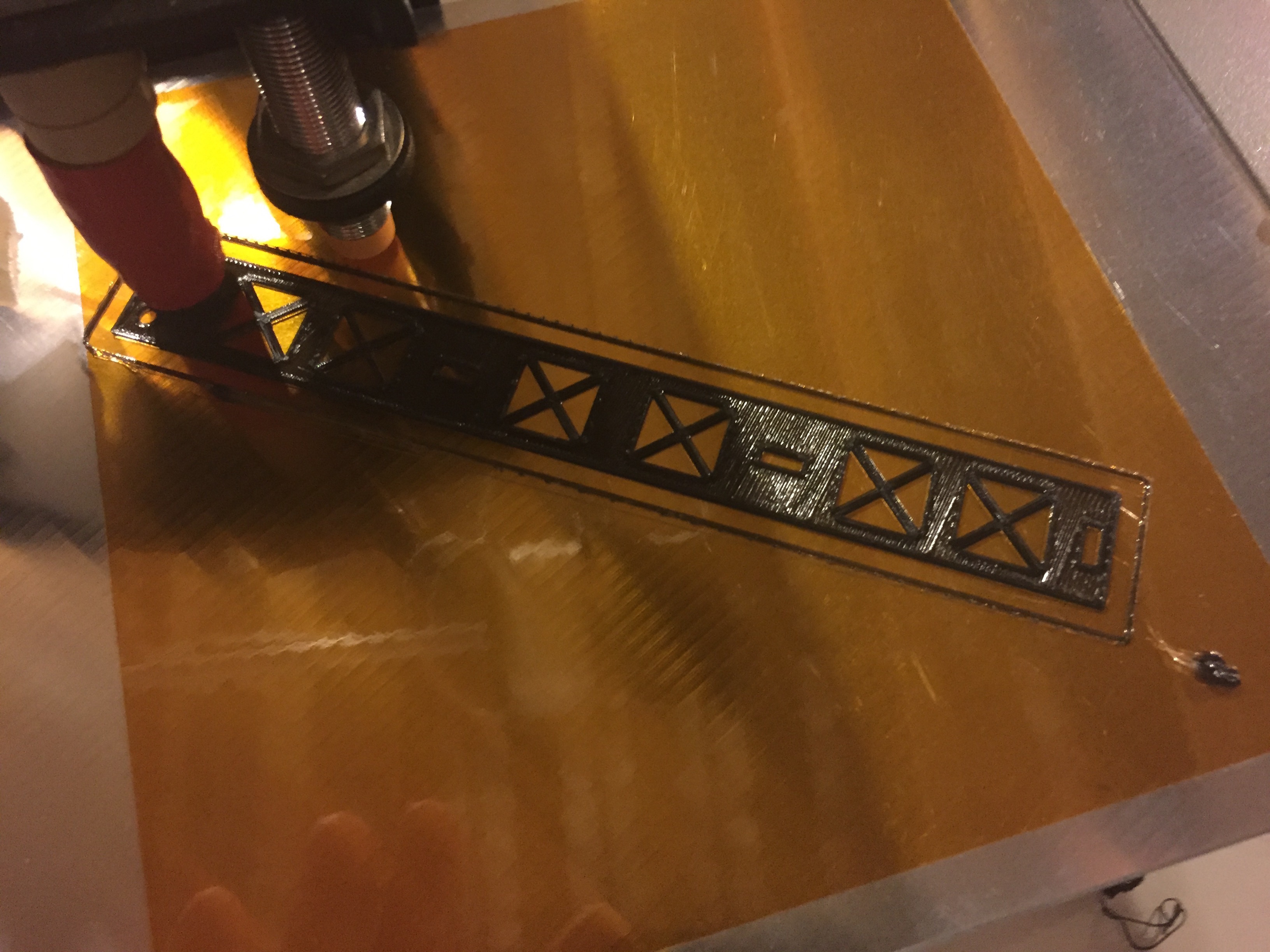
While Printing
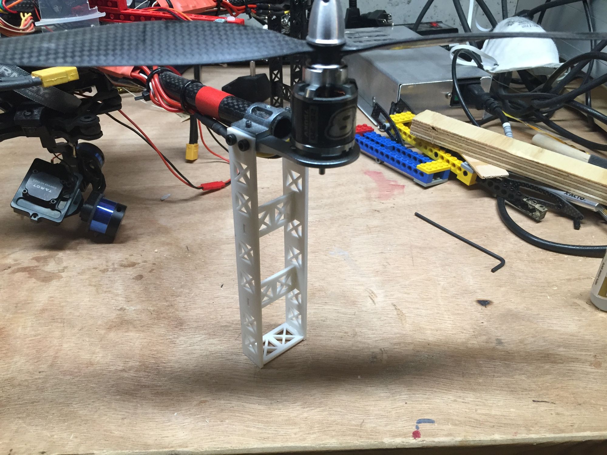
The Parts
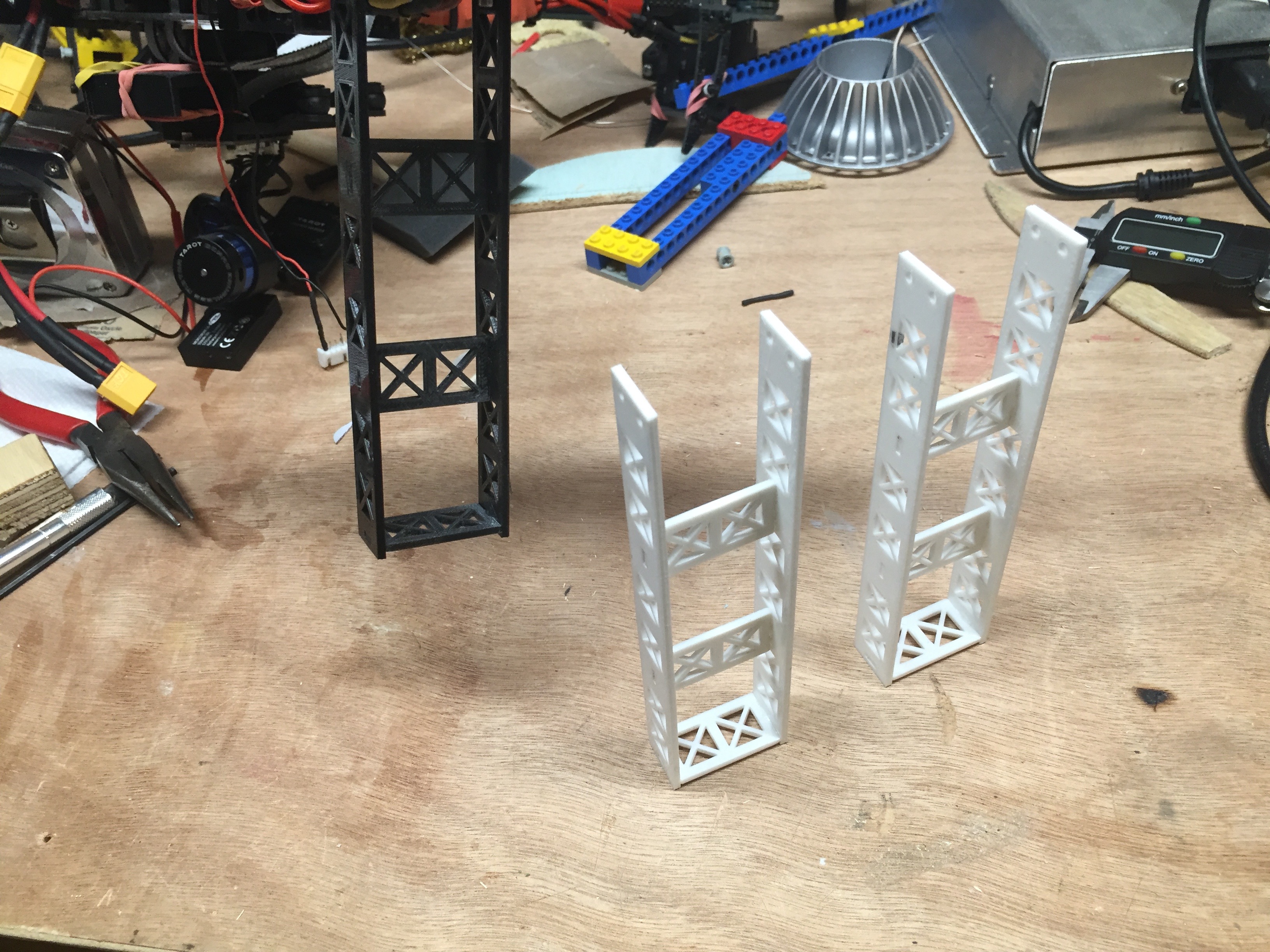
Glued together
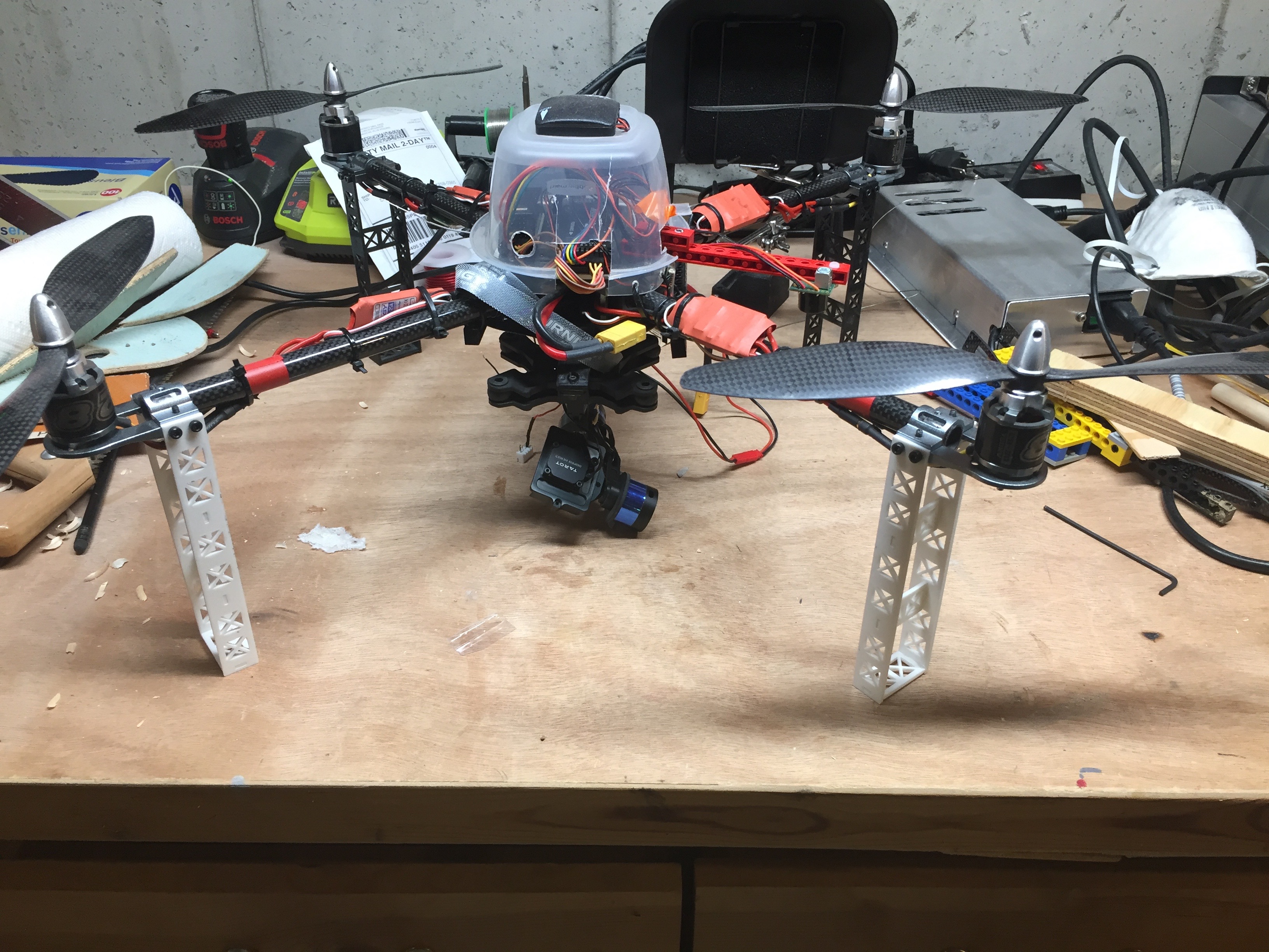
Attached to Quad
Close up
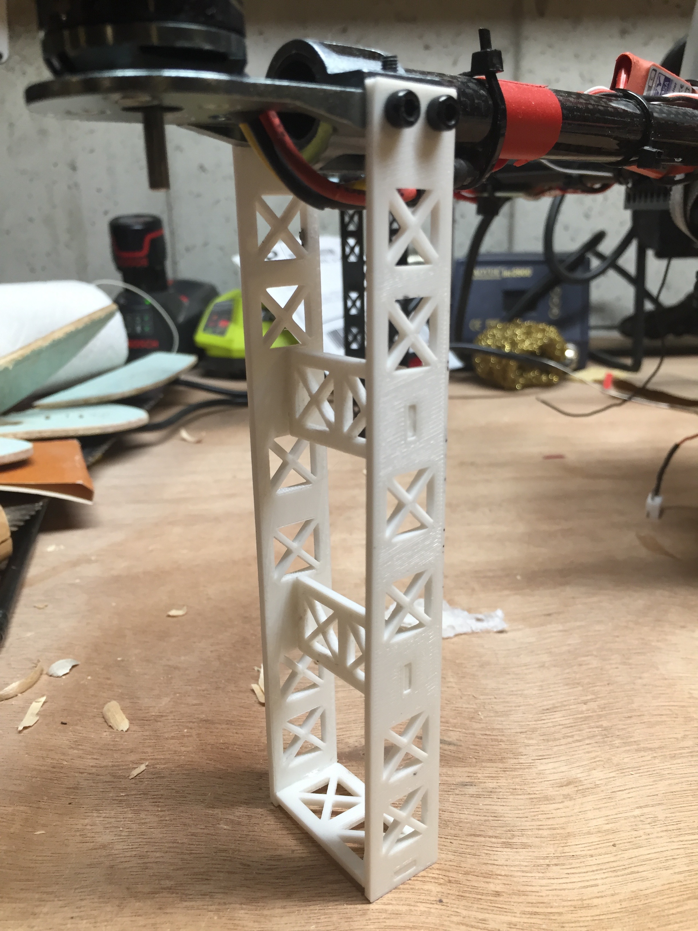
They didn't turn out bad. We'll see if they hold up.
Next up, folding gear!!